- Preliminary: Preparation of symbol chart for various systems & components as per ISS, to study the constructional and operational features for Voltmeter, Ammeter, Wattmeter, Frequency Meter, Multimeter and Rheostat. Study of safety rules.
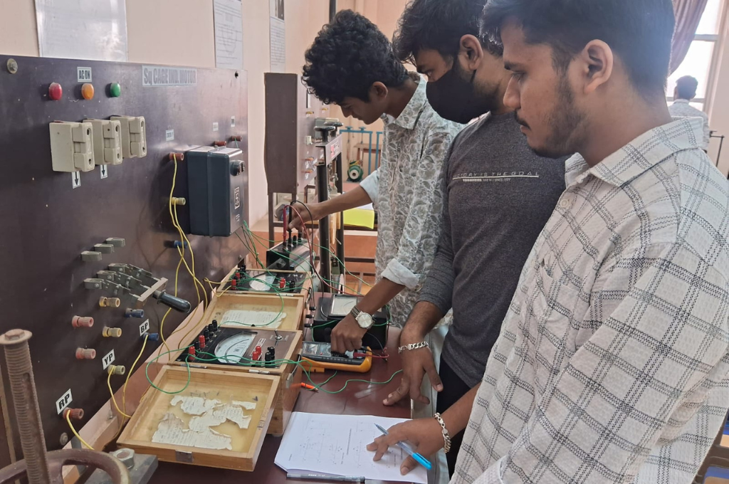
- Demonstration of cut-out sections of machines: DC machine (commutator-brush arrangement), induction machine (squirrel cage rotor), synchronous machine (field winding – slip ring arrangement) and single-phase induction machine.
- Measurement of the armature and field resistance of DC machine by volt-amp method.
- Starting and speed control of a DC shunt motor.
- Study of B-H curve of ferromagnetic core.
- Determination of open circuit characteristics (O.C.C) of DC shunt generator when separately excited at different speeds and excitation levels.
- Calibration of a single-phase energy meter by direct loading.
- Measurement of power and power factor of a single-phase circuit.
- Measurement of earth resistance and insulation resistance.
- Verification of Thevenin’s and Norton’s theorem.

- ACADEMICS
- >
- DEPARTMENTS
- >
- ELECTRICAL AND ELECTRONICS ENGINEERING
- >
- LABORATORIES
LABORATORIES
BASIC ELECTRICAL ENGG. LABORATORY
Experiments


Power Electronics Lab
LIST OF MAJOR EQUIPMENTS
| Sl.No. | Equipment | Quantity |
| 01 | Study of the V-I characteristics of SCR, TRIAC andMOSFET Trainer Kit | 02 sets
01 set |
| 02 | Study of the V-I characteristics of UJT Trainer Kit | 01 set |
| 03 | To measure the latching and holding current of a SCR Trainer Kit | 01 set |
| 04 | Study of the synchronized UJT triggering circuitTrainer Kit | 02 sets
01 set |
| 05 | Study of the cosine controlled triggering circuit Trainer Kit | 02 sets
01 set |
| 06 | Study of the single phase half wave controlled rectifier and semi converter circuit with R and R-L Load Trainer Kit | 01 set |
| 07 | Study of single phase full wave controlled rectifier circuits(mid point and Bridge type) with R and R-L Load Trainer Kit | 02 sets
01 set |
| 08 | Study of the forward converter (Buck converter) and fly back converter (Boost converter) operation Trainer Kit | 01 set |
| 09 | Study the performance of three phase VSI with PWM control Trainer Kit | 01 set |
| 10 | Study the performance of single phase AC Voltage controller with R and R-L Load Trainer Kit | 01 set |
| 11 | Study of the resonant inverter Trainer Kit | 01 set |
| 12 | 3PH,1kva,Isolation Transformer | 01 |
| 13 | Rheostat(2A,220 ohm) | 04 nos |
| 14 | 3PH,3kva, Auto Transformer | 01 |
| 15 | 1PH,1kva, Auto Transformer | 01 |
| 16 | 1PH,1kva, Centre Tap Transformer | 01 |
| 17 | 1PH,1kva,Isolation Transformer | 02 |
| 18 | C.R.O. | 03 |
| 19 | D.S.O. | 02 |
| 20 | Regulated D.C power supply | 03 |
| 21 | 3ph Lamp Load | 01 |
| 22 | Digital Multimeter | 09 |
LIST OF EXPERIMENTS CONDUCTED
1. Study of the V-I characteristics of SCR, IGBT and MOSFET.
2. Study of the cosine controlled triggering circuit
3.To measure the latching and holding current of a SCR
4. Study of the single phase half wave controlled rectifier and semi converter circuit with R and R-L Load
5. Study of single phase full wave controlled rectifier circuits (mid point and Bridge type) with R and R-L Load
6. Study of three phase full wave controlled rectifier circuits (Full and Semi converter) with R and R-L Load
7. Study of the Buck converter
8. Study of the Boost converter
9. Study of the single phase PWM voltage source inverter
10. Study the performance of three phase VSI with PWM control
Electrical Measurement & Instrumentation Lab
LIST OF MAJOR EQUIPMENTS
| Sl.No. | Equipment | Quantity |
| 01 | Kelvin’s double bridge trainer kit | 02 |
| 02 | Maxwell’s Inductance capacitance bridge trainer kit | 03 |
| 03 | Schering bridge trainer kit | 02 |
| 04 | Measurement of R-L-C using LCR meter | 01 |
| 05 | D.C power supply | 03 |
| 06 | Calibration of voltmeter & Ammeter by potentiometer trainer kit | 01 |
| 07 | Energy meter trainer kit | 01 |
| 08 | Ballistic constant setup trainer kit | 01 |
| 09 | Magnetic hysteresis curve tracer trainer kit | 01 |
| 10 | Power measurement by two watt meter method trainer kit | 01 |
| 11 | Digital Multimeter | 14 |
| 12 | C.R.O. | 06 |
| 13 | Function generator | 02 |
| 14 | Voltmeter(0-300v) M.I type | 02 |
| 15 | Ammeter (0-50A) M.I type | 02 |
LIST OF EXPERIMENTS CONDUCTED
| 1. | To measure strain developed in a cantilever beam using strain gauge |
| 2. | Study of temperature voltage characteristics of J type thermocouple |
| 3. | Measurement of linear displacement using LVDT |
| 4. | Measurement of unknown resistance by Wheatstone Bridge |
| 5. | Measurement of unknown inductance by Maxwell Inductance Bridge |
| 6. | Measurement of unknown capacitance usingDe-sauty’s Bridge |
| 7. | Measurement of unknown resistance using Kelvin’s Double Bridge |
| 8. | Measurement of unknown capacitanceusing Schering Bridge |
| 9. | Measurement of unknown inductanceusing Hay’s Bridge |
| 10. | Measurement of unknown inductance Anderson Bridge |


Digital Signal Processing Lab
LIST OF MAJOR EQUIPMENTS IN THE LAB
| Sl No | Name of The Equipment | Quantity | Make | Model | Specification |
| 1 | Computer System (PC) | 27
|
DELL | OPTIPLEX 330 | Intel® Core™ 2 Duo CPU E4500 @2.20GHz, 775 LGA socket,L2 Catch 2048KB,Chipset Intel G31, DDR2 1GB RAM 333MHz Frequency, Dell Monitor |
| 2 | Computer System (PC) | 06
|
LENOVO | Think Center | Intel® Pentium® Dual CPU E2160 @1.80GHz, 775 LGA socket,L2 Catch 1024KB,Chipset Intel G31, DDR2 1GB RAM 333MHz Frequency, 3 Dell Monitor and 3 Lenovo Monitor |
| 3 | DSP Trainer Kit | 05
|
VI Micro System | VSK-6713 | TMS320C6713, Clock Cycle 225MHz, AIC23 Codec, 12 Bit Dual ADC, 12 Bit four DAC Channel, 16 MB SDRAM, 512KB Nonvolatile flash memory, RS232 interface, 4 user accessible LEDs and DIP switches |
| 4 | Cathode Ray Oscilloscope | 01 | Scientific | SM430 | 30 MHZ |
| 5 | Function Generator | 01
|
Scientific | SM5071 | 3 MHz function Generator counter |
| 6 | MATLAB
|
Standalone | MATHWORKS | 2007a | Matlab main module with link to CCS, embedded TI c6000 simulink tool |
| 7 | VI Debugger For 6713 | Standalone | VI Microsystems | Debugger with c code and ASM interface |
List of Experiments
- Familiarization with the architecture of a standard DSP kit.
- Generation of various types of waveforms (sine, cosine, square, triangular etc.) using MATLAB and DSP kit.
- Linear convolution of sequences (without using the inbuilt conv. function in MATLAB) and verification of linear convolution using DSP kit.
- Circular convolution of two sequences and comparison of the result with the result obtained from linear convolution using MATLAB and DSP kit.
- (i) Computation of autocorrelation of a sequence, cross correlation of two sequences using MATLAB.
(ii) Computation of the power spectral density of a sequence using MATLAB, also implementing the same in a DSP kit.
- Finding the convolution of a periodic sequence using DFT and IDFT in MATLAB.
- (i) Implementation of FFT algorithm by decimation in time and decimation in frequency using MATLAB.
(ii) Determine and plot the FFT of a given 1-D signal using DSP kit. Scattering parameters of Circulator /Isolators.
- Design and implementation of FIR (lowpass and highpass) Filters using windowing techniques (rectangular window, triangular window and Kaiser window) in MATLAB and DSP kit.
- Design and implementation of IIR (lowpass and highpass) Filters (Butterworth and Chebyshev) in MATLAB and DSP kit.
- Convolution of long duration sequences using overlap add, overlap save using MATLAB.
- Implementation of noise cancellation using adaptive filters on a DSP kit.


Communication Engineering Lab
LIST OF MAJOR EQUIPMENTS IN THE LAB
| Sl No | Name of The Equipment | Quantity | Make | Model | Specification |
| 01
|
System | 02
|
DELL | OPTIFLEX
330 |
Core2 Duo Processor,1GB Ram,160GB HDD, Monitor, Keyboard, Mouse |
| 02 | CRO | 05
|
SCIENTIFIC
|
SM410 | 30MHZ |
| 03 | Antenna Trainer Kit | 01
|
SCIENTECH | ST2261 | On Board RF & Tone generators |
| 04 | Satellite Communication Trainer | 01
|
SCIENTECH | ST2271 | 1100-1300MHZ
PPL MICROWAVE OPERATION |
| 05 | Fiber Optics | 01
|
SCIENTECH | ST2502 | Two channel with
Transmitter & Receiver |
| 06 | Colour TV | 02
|
BESTA VISION
/SUMSUNG |
Passion | Both manual & Remote |
| 07 | DVD | 01
|
BESTA VISION | Bv 6800 | Both manual & Remote |
List of Experiments
| Sl. No. | Topic |
| 1. | Radiation pattern of Dipole, Yagi, Helical and Slot Antenna. |
| 2. | Study of different blocks of colour TV receiver such as RF amplifier, IF amplifier, sync separator, vertical oscillator, colour picture tube etc and measurement of various voltage signal waveform. |
| 3. | Polarization Detection of Dipole, Yagi, Helical and Slot Antenna. |
| 4. | Measurement of Refractive Index profile, Numerical Aperture. |
| 5. | Attenuation and bending loss/dispersion in a multimode optical fiber. |
| 6. | Measurement of Gain of a fiber communication link using (a) optical fiber, (b) free space. |
| 7. | Establishing and testing an optical Fiber analog and digital Link. |
| 8. | Simulation of a pn sequence generator using MATLAB. |
| 9 | Simulation of direct sequence spread spectrum technique using MATLAB. |
| 10 | Simulation of TDM and WDM using Matlab. |
|
BEYOND SYLLABUS EXPERIMENTS
|
|
| 11 | To establish a direct communication link between uplink transmitter and downlink receiver using tone signal. |
| 12 | To set up an active satellite link and demonstrate link fail operation. |


Electrical Machines Lab
LIST OF MAJOR EQUIPMENTS
| Sl. No. | Equipment | Specification | Quantity |
| 01 | D.C. Rectifier | I/P 440v,O/P (0-230)v,40A | 01 Set |
| 02 | M-G Set – D.C.Shunt GeneratorD.C.Shunt Motor | 3H.P.,230v,7A,1500rpm3H.P.,230v,11A,1500rpm | 01 Set |
| 03 | D.C.Shunt Motor coupled with Alternator | 2H.P.,220v,8A,1500rpm3Ph,415v,1kva,1.5A,1500rpm | 01 Set |
| 04 | Sq. Cage Induction motor | 3ph,3HP,415v,4.5A,1440rpm | 01 Set |
| 05 | Auto-transformer | 1ph,2kva,230v | 01 |
| 06 | Auto-transformer | 1ph,1kva,230v | 04 |
| 07 | Auto-transformer | 3ph,2kva,415v | 01 |
| 08 | Auto-transformer | 3ph,3kva,415v | 01 |
| 09 | Transformer | 1ph,1kva,230v | 05 |
| 10 | Tachometer | Analog type | 02 |
| 11 | Tachometer | Digital type | 01 |
LIST OF EXPERIMENTS CONDUCTED
List of Experiments for Electrical Machine-I Laboratory
| 1. | Load characteristics of DC shunt/compound generator. | |
| 2. | Load characteristics of DC series motor. | |
| 3. | Speed control of DC shunt motor by armature voltage control and flux control method. | |
| 4. | Determination of critical resistance and critical speed from no load test of a DC shunt generator. | |
| 5. | Back-to-Back testing of DC machines (Hopkinson’s method) | |
| 6. | Determination of efficiency and voltage regulation by open circuit and short circuit test on single-phase transformer. | |
| 7. | Parallel operation of two single phase transformers. | |
| 8. | Study of Open delta and Scott connection of two single phase transformers. | |
| 9. | To connect and measure the line voltage & phase voltage of three single-phase transformer in
(a) star-star (Y-Y) (b) star-delta (Y- ) (c) delta-delta (-) (d) delta-star (-Y) |
|
| 10. | Back-to Back test on two single phase transformers. |
List of Experiments for Electrical Machine-II Laboratory
| 1. | Determination of the voltage regulation of an alternator by synchronous impedance method and zero power factor (ZPF) method. |
| 2. | Determination of the V curve and inverted V curves of a synchronous motor. |
| 3. | Speed control of a three-phase induction motor using variable frequency drives. |
| 4. | Determination of parameters of synchronous machine.
a. Positive sequence reactance. b. Negative sequence reactance. c. Zero sequence reactance. |
| 5. | Determination of power angle characteristics of an alternator. |
| 6. | Determination of parameter of a Capacitor start single phase induction motor. |
| 7. | Study of parallel operation of two alternators. |
| 8. | Measurement of direct and quadrature axis reactance of a salient pole synchronous machine by Slip test. |
| 9. | Determination of parameters of three phase induction motor from No Load Test and Blocked Rotor Test. |
| 10. | Determination of Efficiency, Plotting of Torque-Slip Characteristics of Three Phase Induction motor by Brake Test. |


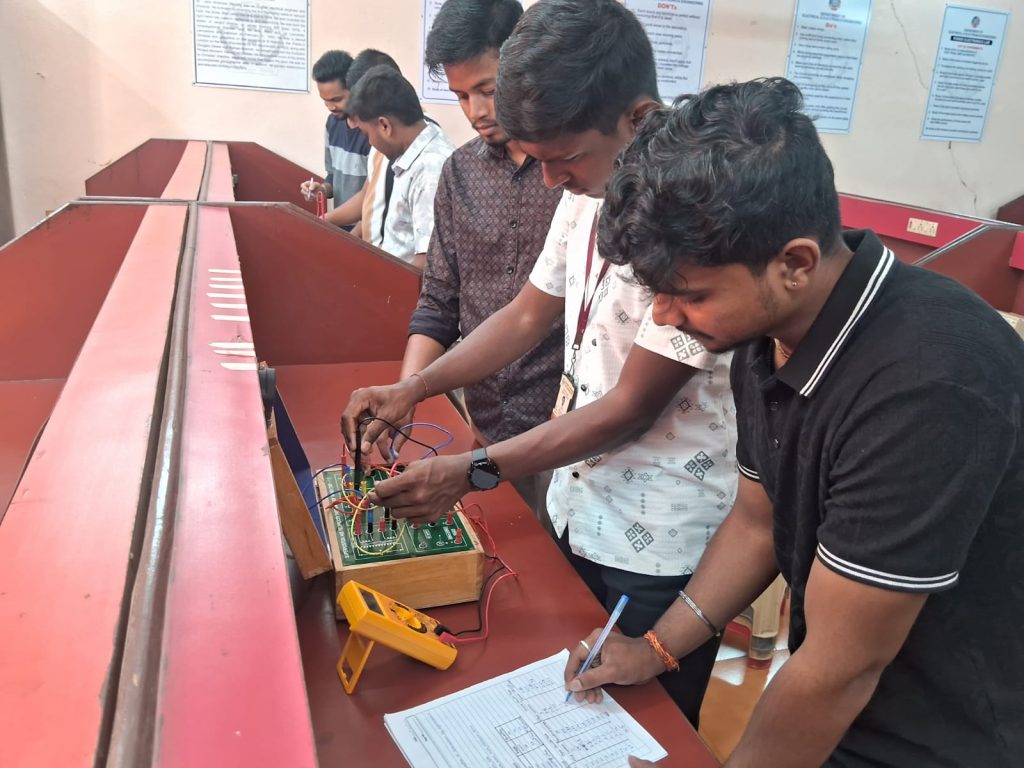
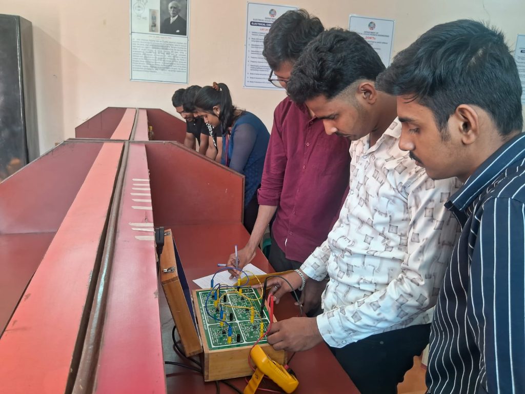
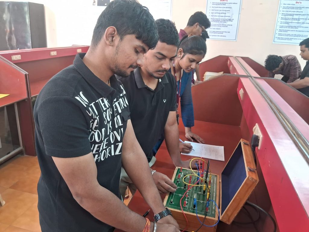
Electrical Circuit Analysis Lab
LIST OF MAJOR EQUIPMENTS
| Sl.No. | Equipment | Quantity |
| 01 | C.R.O. | 03 Set |
| 02 | Function Generator | 04 Set |
| 03 | Verification of Superposition& Maximum Power Transfer Theorems Trainer Kit | 02 set |
| 04 | Verification of Thevenin & Nortons Theorem Trainer Kit | 02 set |
| 05 | Study of DC and AC Transients Trainer Kit | 02 set |
| 06 | Determination of circuit parameters: Open Circuit and Short Circuit parameters Trainer Kit | 02 set |
| 07 | Determination of circuit paramets: Hybrid and Transmission parameters Trainer Kit | 02 set |
| 08 | Frequency response of Low pass and High Pass Filter Trainer Kit | 02 set |
| 09 | Frequency response of Band pass and Band Elimination Filters Trainer Kit | 02 set |
| 10 | Determination of self inductance, mutual inductance and coupling coefficient of a single phase two winding transformer representing a coupled circuit Trainer Kit | 02 set |
| 11 | Digital Multimeter | 19 nos |
LIST OF EXPERIMENTS CONDUCTED
-
1. Validation of Network Theorems using AC circuits (Superposition, Thevenin, Norton, Maximum power transfer)
2. Study of DC and AC transients for R-L, R-C & R-L-C circuits using digital storage oscilloscope 3. Determination of two port network parameters (open circuit and short circuit parameters) 4. Determination of two port network parameters(hybrid and transmission parameters). 5. Frequency response of low pass and high pass filters. 6. Frequency response of band pass and band elimination filters. 7. Determination of self-inductance, mutual-inductance and coupling coefficient of a single-phase two winding transformer representing a coupled circuit. 8. Study of series and parallel connected magnetically coupled circuits 9. Study of resonance in R-L-C series circuit using oscilloscope. 10. Study of resonance in R-L-C parallel circuit using oscilloscope.
Power System Simulation Lab
LIST OF MAJOR EQUIPMENTS
| Sl.No. | Equipment | TOOLS | Quantity |
| 01 | Computer system | MATLAB-2015
& Proteus 8.0 |
36 nos
|
LIST OF EXPERIMENTS CONDUCTED
- Determination of transmission line parameters (inductance and capacitance) for a single-phase line using MATLAB Program / SIMULINK Model. (3Hrs)
- Determination of transmission line parameters (inductance and capacitance) for a symmetrical & unsymmetrical three-phase transmission line using MATLAB Program / SIMULINK Model (3Hrs)
- Determination of Power Angle Diagrams, Reluctance Power, Excitation, Emf and Regulation for Salient and Non-Salient Pole Synchronous Machines using MATLAB Program / SIMULINK Model (3Hrs)
- Modelling and performance analysis of short & medium transmission line using MATLAB Program / SIMULINK Model (3Hrs)
- Study of Surge Impedance Loading of a long transmission line using MATLAB Program / SIMULINK Model (3Hrs)
- Verify the Ferranti effect in a transmission line using MATLAB Program / SIMULINK Model (3Hrs)
- Evaluation of sag in overhead transmission lines with equal and unequal tower heights using MATLAB Program / SIMULINK Model (3Hrs)
- Determination of string efficiency of suspension-type insulators using MATLAB Program / SIMULINK Model (3Hrs)
- Improvement of voltage profile at a load bus using a shunt capacitor using MATLAB Program / SIMULINK Model (3Hrs)
- Study and compare the performance of a ring and radial distributions systems using MATLAB Program / SIMULINK Model (3Hrs)


Control System Lab
LIST OF MAJOR EQUIPMENTS
| Sl.No. | Equipment | Quantity |
| 01 | Position control system trainer kit | 01 |
| 02 | Speed controller trainer kit | 01 |
| 03 | PID controller trainer kit | 01 |
| 04 | Lead Lag network trainer kit | 01 |
| 05 | Relay control system trainer kit | 01 |
| 06 | Data Acquisition system trainer kit | 01 |
| 07 | Anderson Bridges trainer kitSchering Bridges trainer kitKelvin’s doubles Bridges trainer kit | 020101 |
| 08 | LVDT trainer kit | 01 |
| 09 | Strain Gauge trainer kit | 01 |
| 10 | Thermocouple module with thermocouple, water bath, thermometer | 01 |
| 11 | C.R.O | 01 |
| 12 | Computer | 01 |
| 13 | Multimeter | 03 |
LIST OF EXPERIMENTS CONDUCTED
- Study of a dc motor driven position control system.
- Study of speed torque characteristics of two-phase AC servomotor and determination of its transfer function.
- Obtain the frequency response of a lag and lead compensator.
- To observe the time response of a second order process with P, PI and PID control and apply PID control to servomotor.
- To determine the transfer function of a system (network) using transfer function analyser.
- To study and validate the controllers for a temperature control system.
- To study the position control system using Synchroscope.
- To Analyse the Time Domain specifications of Under damped second order system using MATLAB.
- To analyse the stability of the system by using Root locus using MATLAB.
- To analyse the stability of the given linear system using Bode plot using MATLAB.


Microprocessor Lab
LIST OF MAJOR EQUIPMENTS IN THE LAB
| Sl No | Name of The Equipment | Quantity | Make | Model | Specification |
| 1 | 8085 Microprocessor | 13
|
Vi Microsystems | M-85 EB(LED & LCD) | 8-BIT |
| 2 | 8086 Microprocessor | 14
|
Vi Microsystems | M-86 EB | 16-BIT |
| 3 | 8051 Microcontroller | 08
|
Vi Microsystems | M-51 EB | 8-BIT |
| 4 | CRO | 04
|
SCIENTIFIC | SM-410 | 30MHZ |
| 5 | Digital To Analog Converter | 05
|
Vi Microsystems | VBMB-002 | 8/16 BIT |
| 6 | Elevator Simulator | 08
|
Vi Microsystems | VBMB-022 | 8/16 BIT |
| 7 | 8279 Interface Board | 05
|
Vi Microsystems | VBMB-001 | 16 BIT |
| 8 | 8255 Interface Board | 07
|
Vi Microsystems | VBMB-008 | 8/16 BIT |
| 9 | Stepper Motor Kit | 12
|
Vi Microsystems | VBMB-13A | 8/16 BIT |
| 11 | Traffic Light Controller | 08
|
Vi Microsystems | 8/16 BIT |
List of Experiments
- Programs for 16-bit arithmetic operations using 8086.
- Programs for Sorting and Searching (Using 8086).
- Programs for String manipulation operations (Using 8086).
- Programs for Digital clock and Stop watch (Using 8086).
- Interfacing ADC and DAC with 8086.
- Parallel Communication between two Micro Processor Kits using Mode 1 and Mode 2 of 8255.
- Interfacing and Programming 8279, 8259, and 8253 with 8086.
- Serial Communication between two Micro Processor Kits using 8251.
- Interfacing and Programming of Stepper Motor and DC Motor Speed control with 8086.
- Programming using Arithmetic, Logical and Bit Manipulation instructions of 8051microcontroller.
- Programming and verifying Timer, Interrupts and UART operations in 8051
- A design problem using 8051 (A problem like multi-parameter data acquisition system, elevator simulation, traffic simulation, digital clock using LED matrix, etc)
- To measure the distance of the obstacle using ultrasonic sensor and Arduino and display the distance on the LCD/Graphical LCD.
- To read different parameters like temperature, humidity, motion etc. interfaced with Arduino uno/any microcontroller and send these data to the server (like Raspberry Pi) through wireless communication interfaces like Bluetooth, Wi-Fi, ZigBee, etc and store in the database for analytics.
- To design/simulate a security system using RFID module and alert the authorities via SMS (GSM module) with geocoordinates (GPS module) during unauthorised access. Course


POWER SYSTEM LAB
LIST OF MAJOR EQUIPMENTS
| Sl.No. | Equipment | Quantity |
| 01 | To determine location of fault in a cable using cable fault locator | 01kit |
| 02 | Insulation test for transformer oil | 01kit |
| 03 | To study the idmt over-current relay and with different plug setting and time setting multipliers and plot its time-current characteristics | 01kit |
| 04 | To determine A,B,C,D parameters of an artificial transmission line | 01kit |
| 05 | Computer with Matlab | 36 no. |
LIST OF EXPERIMENTS CONDUCTED
Simulation Based Experiment
- Compute Power Flow Solution by using different techniques like GS, NR and FDLF Method
- Economic Dispatch In Power Systems
- Load – Frequency Control Of Single and Two Area Power Systems
- To perform symmetrical and unsymmetrical fault analysis in a power system.
- Transient stability Analysis in a SMIB & Multi machine systems.
Hardware Based Experiment
- To study the IDMT over-current relay and with different plug setting and time setting multipliers and plot its time – current characteristics ( Numerical / Electromechanical)
- To determine the operating characteristics of biased different relay with different % of biasing ( Numerical / Electromechanical)
- Over/Under Voltage Relay ( Numerical / Electromechanical)
- To study the MHO and reactance type distance relays. ( Numerical / Electromechanical)
- To study Over/Under Frequency Relay


Electical Project Lab
LIST OF MAJOR EQUIPMENTS
| Sl.No. | Equipment | TOOLS | Quantity |
| 01 | Computer system | MATLAB-2013&
Proteus 8.0 |
36 nos |
| 02 | Multimeter | – | 10 |
| 03 | Tachometer(Digital) | – | 5 |
| 04 | Digital Multimeter | – | 14 |
| 05 | C.R.O. | – | 06 |
| 06 | Function generator | – | 02 |
| 07 | Voltmeter(0-300v) M.I type | – | 02 |
| 08 | Ammeter (0-50A) M.I type | – | 02 |


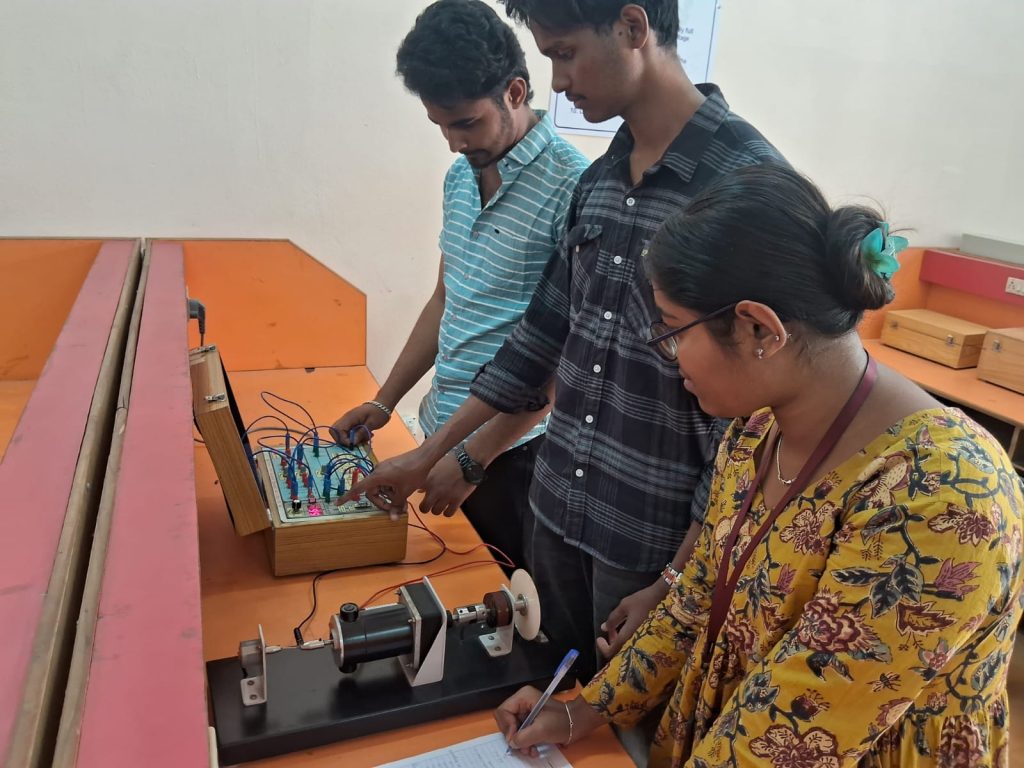
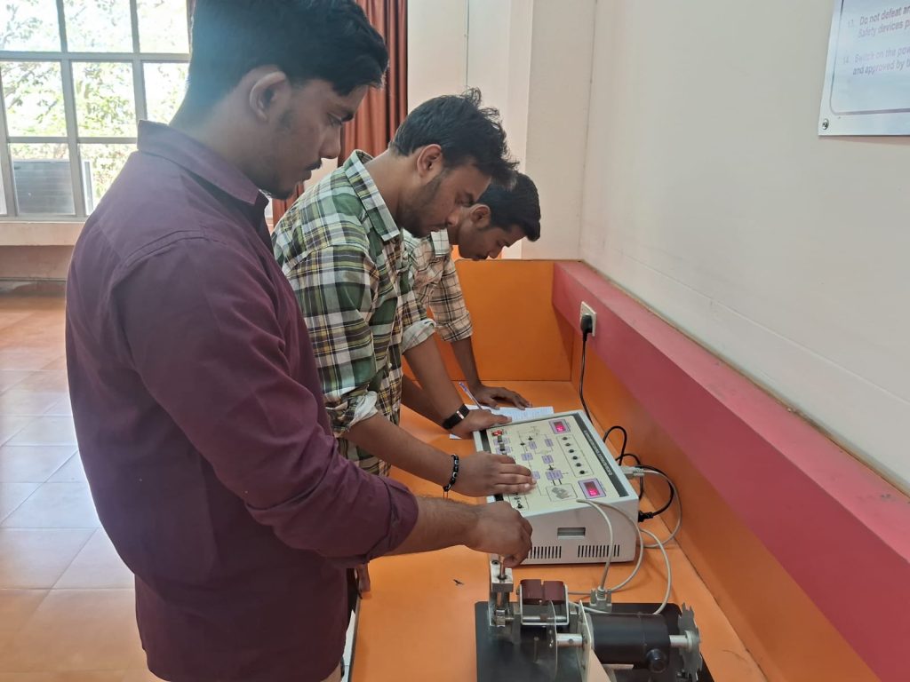
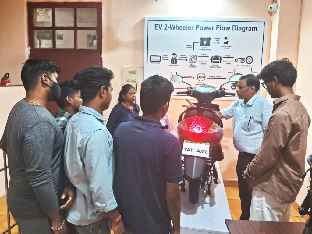
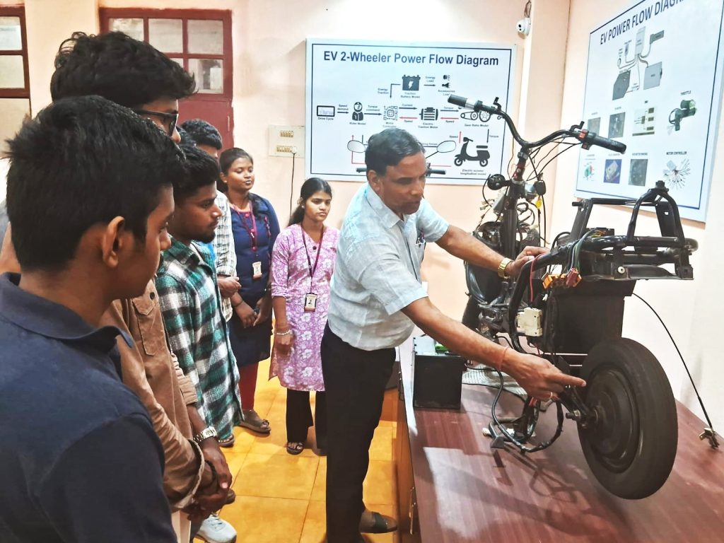
Electric Vehicle Technology Lab
An Electric Vehicle Technology Lab has been set in the department. This lab is equipped with two EV 2 wheelers (Wokinawa make) with one 2 Wheeler cut section model where students are exposed to hands on practice of assembling and dismantling of all EV components. Besides, this lab houses 3 special sections with three wall display TV Units for Mechanical, Electrical and Electronics sections where students are imparted training and demo with EV power train live model, battery pack, traction motor and controller, battery management system and diagnostic tools.
The objective of the Electric Vehicle Technology (EVT) lab is to provide hands-on practical training, skill development, EV internships, and research and development support across a wide range of EV technologies. This learning facility is dedicated to accelerating research and development in areas such as EV design, motor control, battery management systems, chargers, embedded systems, IoT, and automotive electronics. By enhancing learners’ skills, the lab aims to create opportunities and contribute to sustainable employment for students.


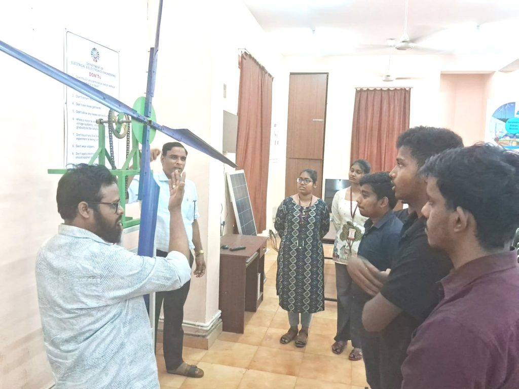
RENEWABLE ENERGY LAB
The Renewable Energy Lab is set up with PV solar panels, solar off-grid setup, solar nano-grid to study the parameters of solar PV system using MPPT and PWM controller. The lab is also equipped with 500watt field model wind turbine, a vertical axis Tulip model and a blade less suction model for students study and training on the renewable energy technology.
Students will explore renewable energy, understanding its benefits in this laboratory compared to the risks associated with non-renewable energy sources. They will gain hands-on experience by building their own solar-powered and wind-powered turbine prototypes, while focusing on cost-efficiency. This mirrors the efforts of modern engineers who strive to reduce the costs of renewable energy, making it more attractive to the public.