List of Experiments
- Preparation of job in fitting section / Study of lathe and turning operation.
- Preparation of job in blacksmith section / Study of milling machine and milling operation.
- Preparation of job in carpentry section / Milling operation on CNC milling machine.
- Study of CNC lathe machine and turning operation on CNC lathe.
- Study of Robot (Pick and Place and Palletizing operation).
- Study of additive manufacturing using 3D printer and product development.
1. Carpentry Section
Study of different hand tools, measuring instruments and equipment used in carpentry work along with safety precautions.
Preparation of Job:
Carpentry job involving different types of joints.
Operations Included:
- Measuring
- Marking
- Sawing
- Planing
- Chiseling
- Mortising
- Tenoning
- Half-lap joint
- Mortise & Tenon joint
- Nail joint
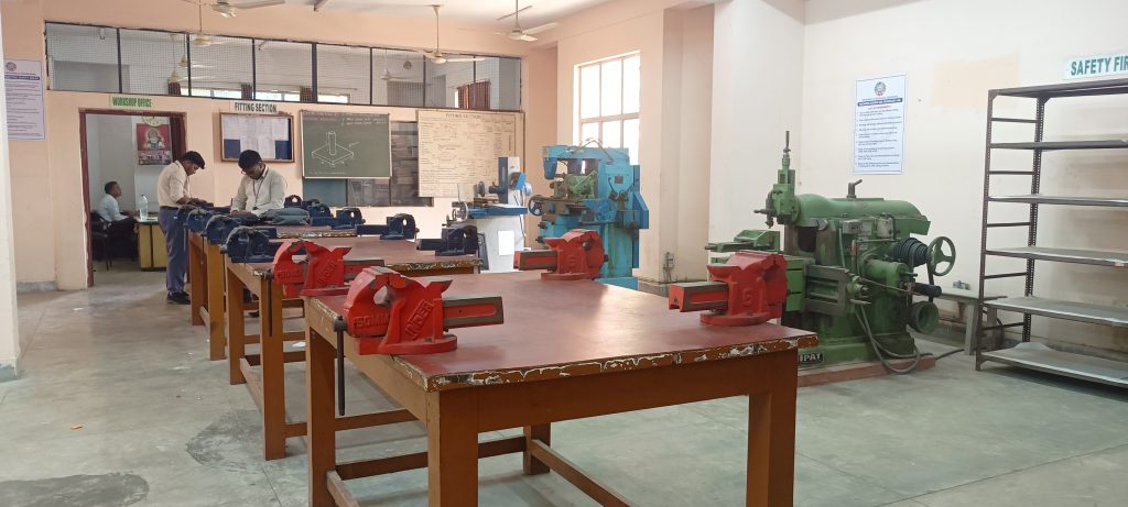
2. Fitting Section
Study of different hand tools, measuring instruments and equipment used in fitting work along with safety precautions. Study of drilling machine and grinding machine.
Preparation of Job:
Paper weight / Square or rectangular joint (male-female joint).
Operations Included:
- Measuring
- Marking
- Filing
- Sawing
- Drilling
- Tapping
- Dieing
- Punching
3. Blacksmith Section
Study of different hand tools, equipment and open hearth furnace used in blacksmith work. Study of different heat treatment processes and safety precautions.
Preparation of Job:
Weeding hook / Chisel.
Operations Included:
- Measuring
- Marking
- Cutting
- Upsetting
- Drawing down
- Bending
- Fullering
- Quenching
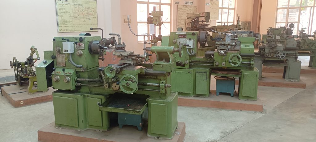
4. Turning / Milling Section (Conventional & CNC)
A. Lathe Machine
- Study of lathe machine
- Different parts and applications of lathe
- Study of measuring and marking instruments
B. Milling Machine
- Study of milling machine
- Different parts and applications of milling machine
- Study of measuring and marking instruments
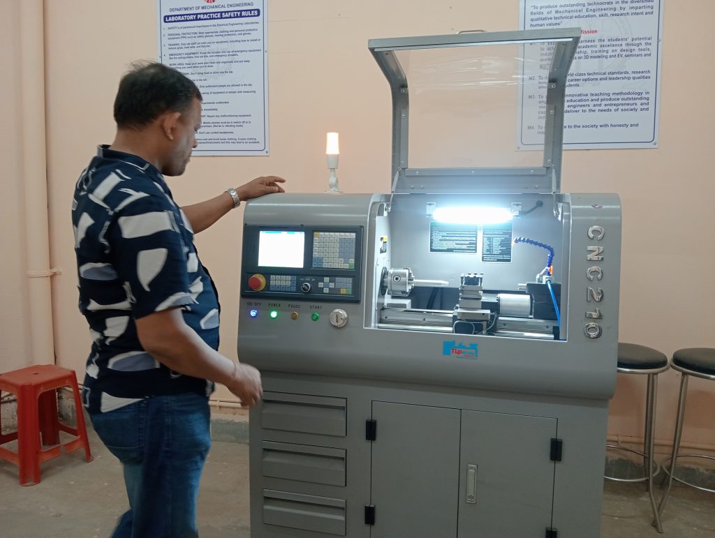
C. CNC Lathe
- Study of CNC lathe machine and its parts
- Part programming for turning operations
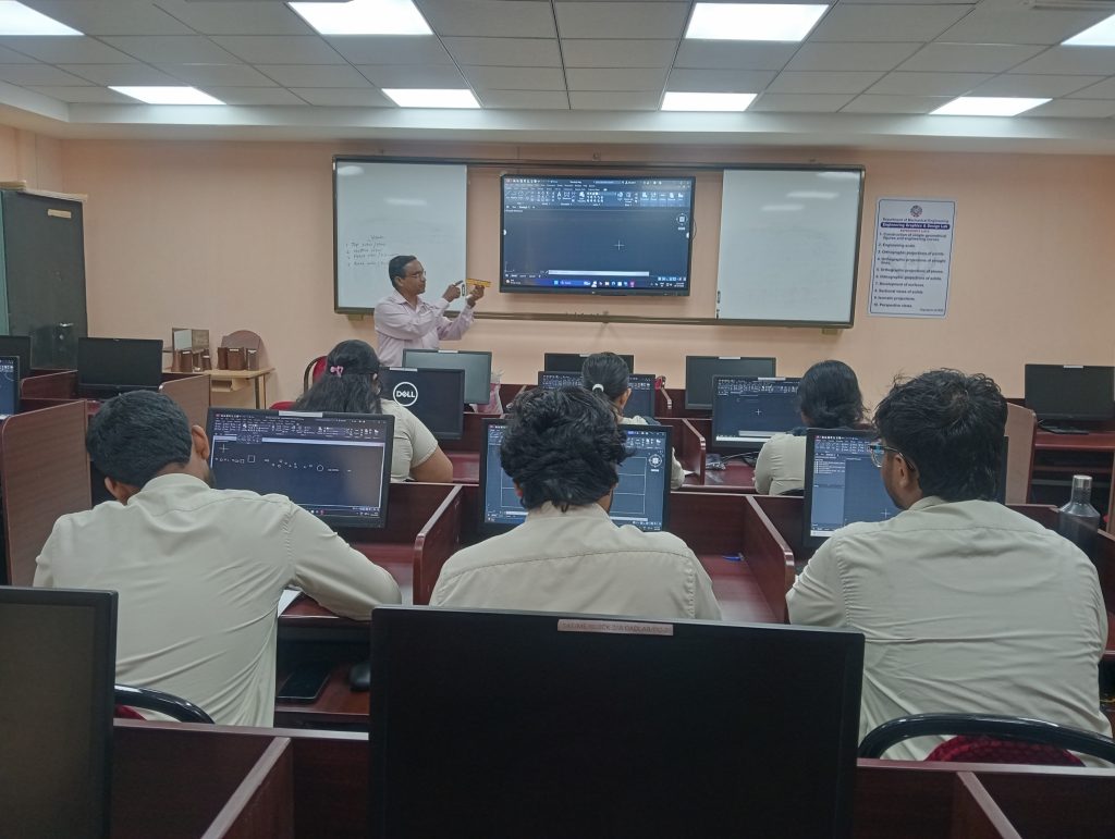
D. CNC Milling Machine
- Study of CNC milling machine and its parts
- Part programming for milling operations
5. Robotics Lab
- Study of robot
- Pick and place operation with demonstration and explanation of code
- Palletizing operation with demonstration and explanation of code
6. Additive Manufacturing Lab
- Study of 3D printer
- Demonstration of additive manufacturing operation and product development